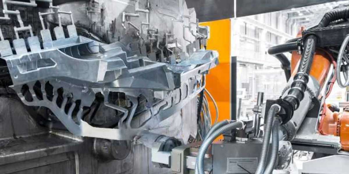
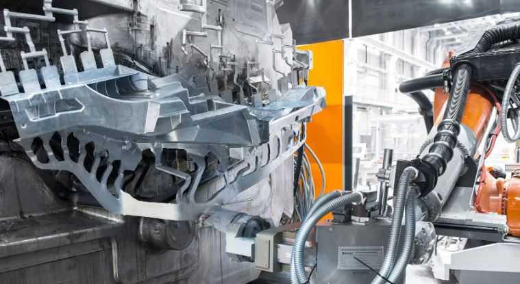
Comprehensive Aluminum Die Casting Design Guide
Here at Diecasting-mould.com, we want all of our customers to feel empowered when designing for die casting production. In this extensive guide, we'll cover every aspect of aluminum die casting design to ensure manufacturability and quality casting outcomes.
Material Selection
The aluminum alloy used has a significant influence on properties like strength, fluidity and tolerance. Some common die casting alloys include:
| Alloy | Characteristics |
|---|---|
| A380 | Excellent castability and strength |
| A356 | Higher strength, lower fluidity than A380 |
| AC4C-F | Higher strength and thermal conductivity |
Consult suppliers for guidance on selecting the right alloy for your application.
Draft Requirements
Draft refers to the taper or inclination of die cores to facilitate part ejection. Minimum draft values vary based on part depth and configuration:
Wall Thickness Guidelines
Proper wall thickness distribution is critical for optimal metal filling and minimizing defects. Recommended ranges are 0.25-5mm for most aluminum die casts.
Ribs and Bosses
These features increase part stiffness without excess material. Design ribs and bosses according to the following:
Undercuts and Side Cores
Features parallel to the parting line require side cores for manufacturability. Strategies to avoid undercuts include:
- Redesign for draft-friendly orientation
- Utilize side cores if absolutely necessary
Allowances for Machining
Accounting for machining during the design stage promotes first-pass quality. Recommended machining allowances are 0.010-0.050 inches, depending on part size, features, and precision required.
Draft Calculators and References
Use practical tools like draft calculators and aluminum casting reference books to simplify part design. Example calculator layout:
Working with Suppliers
Consult experienced aluminum die casting manufacturers during the design phase for feedback on factors like material selection, tolerancing, draft, and producibility. Iterative collaboration streamlines the process.
Simulation and Prototyping
CAE tools and 3D printing facilitate verification of part functionality and manufacturability prior to tooling. Make refinements indicated through these pre-production steps.
Annotate Drawings Fully
Provide suppliers with complete drawings specifying all relevant data including surface finish, tolerances, bill of materials, heats and finishes, and production quantities.